Chat application use case diagram in Description UML.FRI It's aimed towards diagram types commonly used by people involved in IT.Main Features:Currently, it's possible to create and edit:- UML class diagram - UML object diagram - UML activity diagram - UML use case diagram- UML state diagram - Flow chart diagram.
With only a few steps, you will finish a good-looking use case diagram with Edraw. Explore the simplicity and convenience of making user case diagrams from this article.
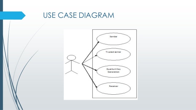
Use case diagram allows you to model system functions, and present how actors interact with those functions. In this page, you will learn how to draw an excellent user case diagram with pre-made shapes and smart connecting.
Built-in Use Case Symbols
Start a New Use Case Diagram Drawing Page
1. Start Edraw, on the File menu, point to New.
2. Click Software from the Template Category, and then double click Jacobson Use Case icon to start a new page.
3. On the left, a library for Jacobson Use Case Diagram is open. All the commonly used symbols are included.
Add a System
From the built-in Use Case Library, drag a block shape on the page to represent the system. Resize the block by dragging the control handles. You can fill it will a color, and name the system using Text tool.
Add Actors
Hey say jump discography. From the library, drag a built-in actor symbol, and drop on a suitable position of the canvas.
Add Use Case
From the library, drag a built-in use case symbol, and drop in the system block. To resize the use case shape, select it and drag the control handles. Double click on the shape to add text.
Connect Actor with Use Case
Draw a connector using Connector button under Home tab. To change connector style, you can right click the mouse and choose Select All Connectors, then click Line button to set line style. To set the line style ahead, you can right click the mouse, and choose Set Default Theme, Arrow..
Apply a Theme
Under the Page Layout tab, a group of nice themes with advanced colors and effects is available for you to choose.
The Final Use Case Diagram
Download a free trial and see first-hand how quickly and easily you can create great-looking use case diagram.
Made with
Related Solutions
The use case diagram (behavior scenarios, precedents) is the initial conceptual representation of the system during its design and development. This diagram consists of actors, use cases and relationships between them. When constructing a diagram, common notation elements can also be used: notes and extension mechanisms.
The essence of this diagram is as follows: the designed system is represented as a set of actors interacting with the system using the so-called “use cases”. In this case, an actor (acting person, actant, artist) is any object, subject, or system that interacts with a simulated system from the outside. In turn, the “use case” is a specification of the services (functions) that the system provides to the actor. In other words, each “use case” defines a certain set of actions performed by the system when interacting with an actor. At the same time, the model does not reflect in any way how this set of actions will be implemented.
View and Download Sony Handycam DCR-PC115 service manual online. DIGITAL VIDEO CAMERA RECORDER. Handycam DCR-PC115 Camcorder pdf manual download. Also for: Handycam pc115e, Handycam pc120bt, Handycam pc120e. Included components may vary. Announcement for customers using PlayMemories Home, Action Cam Movie Creator, MVR Studio and Sony Raw Driver -. Termination of the Map View function in PlayMemories Home (for Windows) and the map display function in the GPS Image Tracker -14 February 2019. In the GPS Image Tracker. Included components may vary by country or region of purchase: RMT-811. Notice to customers using PlayMemories Home, Action Cam Movie Creator, MVR Studio and Sony Raw Driver. Termination of Map View in PlayMemories Home (Windows version) and the map display function in GPS Image Tracker. Windows 7 Compatibility. Installing the correct driver (Windows 7 only) Note: If your PC runs Windows Vista or Windows 8, you won't need to do this. Once your camcorder is connected, you will need to verify that the proper driver has been selected by Windows 7. Windows 7 comes with two i.LINK/IEEE 1394 drivers; a new one and a legacy one. Driver sony handycam dcr-pc115e windows 7 1. The following is the important information of Sony DCR-PC115E installation driver. Click on Download Now and a File Download box will appear. Select Save This Program to Disk and a Save As box will appear. Select a directory to save the driver in and click Save. Locate the driver file using Windows Explorer when the download has completed.
In the structural approach, the analogue of the use case diagram is IDEF0 and DFD diagrams, use-work options (IDEF0) and processes (DFD), and actors — external entities (DFD).
This sample was created in ConceptDraw DIAGRAM diagramming and vector drawing software using the UML Use Case Diagram library of the Rapid UML Solution from the Software Development area of ConceptDraw Solution Park.
This sample shows the types of user’s interactions with the system and is used at the registration and working with the database system.
Example 1. Registration System. UML Use Case Diagram
Using the libraries of the Rapid UML Solution for ConceptDraw DIAGRAM you can create your own visual vector UML diagrams quick and easy.
UML Resource:
TEN RELATED HOW TO's:
Cisco Routers. Cisco icons, shapes, stencils and symbols
Network infrastructure planning is a very important process in the network construction, and the share of time allocated to this within the scope of the entire project may reach 60-80%. A competent and thorough approach to planning contributes to the quick investment return, and also increases the reliability and flexibility of the final system, reducing the probability of additional costs related to the incorrect implementation. Any planning begins with an analysis of the business requirements to the final system. Basic network parameters, which should be assessed are the scalability, accessibility, cost, speed and safety. Speed and cost are often mistaken for the most important parameters, and the rest of the parameters aren't even remembered. This is not entirely correct. Initially, it is necessary to assess the business plans for the future, because sometimes it is more profitable to invest more money in the beginning. If the business is to develop, then, consequently, demands onPicture: Cisco Routers. Cisco icons, shapes, stencils and symbols
Diagramming Software for UML Composite Structure Diagrams
UML Composite Structure Diagram shows the internal structure of a class and the possible interactions at this structure.Picture: Diagramming Software for UML Composite Structure Diagrams
How To Create Project Report
ConceptDraw PROJECT contains an extensive tool set to help project managers. The rich data visualization capability that is provided by ConceptDraw products helps you create project dashboards, one-click reports, multi-project views, Gantt charts, and resource views. Let′s learn how to get maximum value using ConceptDraw PROJECT!Example Process Flow
A flowchart is a picture of the separate steps of a process in sequential order. ConceptDraw DIAGRAM is a Process Flowcharts software. This software includes basic package of process flow examples. The software contains object libraries with vector stencils that allows you use RapidDraw technology. By clicking on direction arrows you can add a new object to the flowchart.Related Solution:
Deployment Chart Software
ConceptDraw DIAGRAM extended with Matrices solution from the Marketing area of ConceptDraw Solution Park is the best Deployment Chart Software. The Matrices solution offers you the useful tools for creating Deployment Charts in just minutes. The Deployment Charts designed with ConceptDraw DIAGRAM are vector graphic documents and are available for reviewing, modifying, converting to a variety of formats (image, HTML, PDF file, MS PowerPoint Presentation, Adobe Flash or MS Visio XML), printing and send via e-mail in one moment.Related Solution:
Pyramid Diagram
When thinking about the process of decision making, it's easy to imagine it as a pyramid. We will look at a three level pyramid model as an example. Operational decisions are first that come to mind, and it's the first level. Tactical and strategic decisions are the second and the third levels. Pyramid (triangle) diagrams are used to show some hierarchical data. Because to the pyramid form of diagram, each diagram slice has a different width. The width of each segment depends on its hierarchical level. The current image illustrates the model of information system types. Most graphically the model can be represented as a three level pyramid. The first level shows a system of transaction processing It is concentrated on operational tasks. The second level is devoted to tactical solutions of the information system management. And at least, the third level addresses strategy and represents the executive information system. This three level pyramid sample is supplied with the ConceptDraw Pyramid Diagrams solution from Marketing area of ConceptDraw Solution Park.Related Solutions:
Subway Train Map
You want create a Subway Train Map fast and easy? Use the excellent tool - ConceptDraw DIAGRAM diagramming and vector drawing software. Extended with Metro Map Solution from the Maps Area, it is the best for drawing various types of metro maps.Related Solution:
Genomics
Genetic engineering is moving in a rapid fashion. There are new discoveries occurring at an incredibly fast pace. This map was created from content found at 'FAQ About Genetic and Genomic Science' (National Human Genome Research Institute, www.genome.gov) and shows how simple in is to use a map structure to explain complex subjects. The content from this map and maps similar to this can be used with the eLearning for Skype solution for ConceptDraw MINDMAP to present complex information in a simplified manner.Related Solution:
Create Sophisticated Professional Diagrams - Simply
ConceptDraw DIAGRAM is a powerful software that helps you create professional and easy drawing diagrams for business, technology, science and education.Picture: Create Sophisticated Professional Diagrams - Simply
SWOT Matrix Template
The strategic balance is a combination of factors that can both positively and negatively affect the activity of the company. To know the factors that influence the organization success, managers should use SWOT matrix template that will define the potential inner strengths and weaknesses and potential external opportunities and threats. This matrix does not contain a ready solution, but allows to streamline all the available information. This is a handy template of a SWOT matrix. It can serves as a visual guide for management students. To simplify the task, on the left and on the right we have added hints with examples of external and internal factors. This template one can found among numerous templates of SWOT and TOWS matrices that are included in the the eponymous solution by ConceptDraw Solution Park.Related How To's